Tuesday, August 16, 2011

CNC Plasma Cutter

I took a CNC plasma cutting class tonight at TechShop.  It was really well run by this guy that does custom tools for working on old muscle cars named John.


He had us cut out a frame support bracket that welds onto some muscle car.  We cut it out of 12ga mild steel (.110" thick).

The cutter is mounted to an x,y gantry that's computer controlled.  You improt a .dxf file of whatever 2D shape you wanna make and then convert it to G code which controls two steppers.  The up and down movement of the nozzle is controlled with a different program that lives on the machine and you don't control.  The machine can easily hold a 4'x8' sheet.


CNC Plasma cutter setup at TechShop
There's a water bath below (actually touching) the sheet steel that absorbs any noxious fumes generated when the plasma arc obliterates the metal its cutting.  Apparently there's a plasma arc that's created with high voltage and current (we used 60A at 144V!) that jumps from the nozzle to the metal you're cutting.  You can't cut anything that doesn't conduct electricity btw.  But it basically melts the metal immediately and then a swirling jet of air comes through the plasma arc and blows the metal out of the way.  Essentially it acts very similar to an end mill except that instead of a spinning sharp tool edge, you have a super-hot spinning arc.  They even refer to climb cutting and conventional cutting in the class to demonstrate that the quality of the cut with a plasma cutter depends on which side of the arc you cut based on your direction of travel.  Basically, if you're going in a straight line, you get a better cut on the right side of the arc than the left.

There's some software that you use to import your geometry called partworks.  It lets you convert to G-code which gets loaded on the machine.
Software program

Then you run the thing.

Wear glasses when looking at this picture
Close-up of nozzle
Nozzle pieces.  The one with the fins is the electrode.
There are basically two electrodes/nozzles that are used (at least by John).  You can use a 40A or 60A nozzle.  40A would be for thicknesses less than .100.  You can cut stainless steel up to 1/2" thick with this thing!

There's a pretty decent bezel angle created when you cut and it varies greatly depending on feed rate but is generally around 3degrees.  It seems like the slower you cut, the more bezel angle you get, but I can't remember why that sticks in my mind.  If you cut too slow, the arc acts erratically because the metal gets blown away where you're cutting and the nozzle is essentially sitting over free space so it looks for the nearest metal to jump to.  You get some pretty jagged cuts this way.  This isn't precision cutting by any means, but we cut out some decent sized pieces of mild steel in a matter of minutes.

Slag on bottom of part
As you can see from the photo, the slag created by the plasma arc is significant.  This ends up on the bottom side of the part.  The top looks pretty clean.  You can break off this slag with your finger, so it's not much of a problem, but takes some post-processing to finish.

Gonna try and make some moped chassis using this thing.

Sunday, August 14, 2011

Lake Jordan

Took a break from the moped and hit the lake this weekend with some lovely ladies.

Ready for some water.
Started out as a crazy trip.  We drove to the lake in a violent rain-storm.  My wipers were on high.  But when we got there it had slowed to a drizzle.

Everyone's wearing jackets in the middle of Aug in NC?
After about an hour, the sun came out and we hit the water for some relaxation.

Carson, Amy, Dhvania, Sophia and some inflatables.
Say what?
Sophia and Dhvania
Dhvania and Amy playin fris
Then we decided to hit the water for some wakeboarding.

Headin outside

About to eat it.
Amy gettin up
Amy ready to carve a nice line
And that wraps up a nice day at Jordan.

Thursday, August 11, 2011

Anodizing

So I decided to anodize the head.  I took a class at TechShop RDU where they teach you to anodize aluminum in one of their back rooms.  They basically have a large wooden box filled with kitty litter that has a bucket of Sulfuric acid sitting in the middle.  A 2x4 is strapped across the top with a couple aluminum bars with screws in them mounted to the top.  The screws are where you hang your parts from.  The aluminum bars are attached to the positive and negative of a power supply.  There's a bucket of dye also (red or blue).

TechShop RDU Anodizing Rig

First thing i had to do was mask off the critical areas: the spark plug hole and the top of the combustion chamber.  I couldn't just use a SS bolt to plug the spark plug hole.  Apparently sulfuric acid eats SS pretty quickly.  So I fashioned a threaded plastic rod and some nuts together to form an encapsulating assembly.

Masking rod assembly
Then I masked the sealing surfaces with masking tape.

Masking tape on the spark plug hole
Masking on the top of the combustion chamber section
Then added the plastic encapsulating assembly.

Bottom side
Top Side
Next I bead blasted the surface to make sure the surface was even.  Then I had to clean any oil off of the aluminum.  Apparently even oil from your fingers can cause blotchy looking spots in your anodize.  Did this by soaking it in a bucket of warm water with some dish soap for 1/2 hour and then rinsing.

Cleaning the head
The next step was to hang the assembly.  I wrapped 4 wires around the fins on four sides of the head and then wrapped them together so they'd hang off of one of the screws.

Hanging head from 4 aluminum wires and dropping it in the Acid
Then I closed the lid(s) on the top of the bucket and turned the power supply on.  As you can see from the above picture, there are two hanging plates on either side of the bucket.  These are the cathodes.  They're connected to the negative side of the power supply.  The Al wires going to the head are connected to the positive side of the power supply.  The current travels from the PS, down into the head through the haning wires, through the sulfuric acid, and back through the cathode plates.  This causes a reaction at the surface of the aluminum to oxidize it.  Basically rusts it or creates aluminum oxide.  At the same time, the acid eats away at this oxide layer, creating a bunch of craters in the surface of the oxide.  These holes or craters are what allows the dye to hold onto the part later.  Or so I'm told.

Bucket of sulfuric acid with 18A of current running through it
Apparently surface area is pretty critical when anodizing.  First, you need to have equal or greater surface area on your cathode(s) as you do on your anode (part).  To figure out how much surface area I had on my head, I had to model it up in SolidWorks and let it calculate it.  Turns out its about 225 sq. inches.  The cathode plates are about 9x9 so their surface area is around 162 sq. each (front + back) or 320 sq. inches total with both plates, so I was fine there.  The other thing to consider in regards to surface area is current density.  The recommended surface density is 12Amps per square foot per hour.  An hour seems to be the recommeded time, but if you can't reach the current density in an hour, then you just extend the time.  The power supply they have maxes out at 18A, so I cranked it up to that since I have a little over 1.5 sq ft.  Close enough.

Power Supply
I let the head sit in the acid for an hour at 18A.

Soaking in a nice electric acid bath
Another thing to consider is the temperature.  If you let the bath get too hot, the chemical reaction isn't as good and your part doesn't anodize properly.  I noticed that the bucket was getting hot to the touch over the course of the hour, but there was no way to cool it, so I had to live with it.  Some people add cooling elements to their baths which would be a good idea here.  You're supposed to keep the bath around 70 deg. F.  I'm sure mine got higher than that.  It was about 100 degrees outside.

In the mean time, I got the bucket of red dye ready.  I wanted to match the color of the bike, so the red was perfect.

Red dye bath
Apparently, its a good idea to warm up the dye bath to get it to stick to the aluminum, so I warmed it up in the microwave to just below boiling.

After the hour was up, I removed the head and rinsed it off good with water.  I then dunked it in the red dye.

Dunking in red dye bath
After the recommended 20 min in the warmed red dye bath, I pulled it out to see what masterpiece I'd created.

Coming out of dye bath
Looked ok at first, but after rinsing, it looked like this.

Anodized!
Looks like ****!  I was pissed.  I'd spent so much time prepping for this moment and it came out terrible.  I did some reasearch in the books they have on anodizing and found out that cast aluminum doesn't anodize well because it's typically got a bunch of different grades of aluminum mixed in that aren't too pure.  I guess I confirmed that theory.  Other than the junky cast aluminum, the only other thing I can think of that wasn't "as recommended" was the temperature of the bath getting too high.  Not much I could do about that though.

WTF Yo?
 After soaking in the red dye bath, it is recommended to seal it with a sealer.  They didn't have any sealer there, and recommended using a bath of boiling water.  You're supposed to soak the entire part in the bath for 5-10 min.  This apparently seals or locks the die into the part.  I didn't bother with this step because, well, look at it.

So anyway, it was a learning experience at least.  I think I'm just gonna spray paint it black now.  I'll sand blast off whatever anodized surface layer there is on there and get a spray can from HD and call it good.

Sunday, August 7, 2011

Wheels

I'm basically at the point now where I have to start rebuilding with the new frame.  I'm at the bottom of the teardown/rebuild curve if you will.  Which means I need to focus on the wheels.  I bought these really cool 3 spoke wheels online.

 
Front 3 spoke wheel test fit

Rear 3 spoke wheel test fit
Of course, they aren't exactly matching.  The thru bolts that hold the wheels together are slightly bigger than the old snowflake wheels, so there's some trouble fitting the old hardware to the new wheels.

New wheels look sweet!

On the rear wheel, there's a sprocket that connects the chain to the motor (big one) and then on the other side, there's a freewheel that connects the rear tire to the pedals.
Blasted 23T freewheel with French Threads

Well, this freewheel is a ***** to get off.  Turns out you need a custom spanner wrench to get this baby free, so I machined one up and started after it.

Freewheel after removal with custom spanner

It was on there good, but after some teeth grinding and hammer blows, it came free.  However, when I went to put it on the new custom wheels, it would only get a couple turns and then jam.  Fuck!

After some web searching, I found out that the stock wheels were made in France and have a metric thread pitch of 25.4mm.  Almost every other freewheel has threads with a 24mm pitch.  So it aint gonna fit.


I set off around Raleigh to different moped shops and tried to track a freewheel down.  None of the places in town have anything cause they mostly produce scooters (lame).  Even that electric bicycle shop on Hillsborough didn't have anything for me.  But luckily, I stumbled across this old dingy shop called Cycle Logic next to a tattoo and piercing shop.  I went in and asked for a freewheel and this old codger started digging through a pile of sprockets and gears and came up with one that was almost perfect.  I couldn't believe it.  I brought the wheel in and bam, it went right on.  Only difference was it has 22 teeth instead of 23.  Not  a big deal.  Will be slightly harder to pedal, but I should be faster on the downhills if I use it as a bike.  $15 later and I was out the door.

22 Tooth Freewheel.  Made in Taiwan.
Dude charged me tax though.  I thought this weekend was tax free weekend here?

So anyway, back to the project.  Now that I had the freewheel, I was good to go and put things back together.  The new wheels came with their own drum brake hardware, but it didn't quite match up with the geometry of the forks, so I decided to put the hardware from the old wheels on these new ones.

Old Snowflake Wheel with Drum Brake
Drum Brake
The new drum brakes go in, but I have to use the old wheel shafts which are slightly smaller than the new shafts, and don't quite fill up the bearings inside the wheels so there's a bit of slop between the shaft and wheel.  Not good cause its putting pressure on the drum brakes, making things bind.  So my options are:

1.  Drop the new drum brakes in with the new shafts and modify the forks to work
2.  Try and use the old smaller shafts with the old drum brakes and live with the slop
3.  Forget this whole drum brake idea and get some disc brakes on this bad boy

Yeah, I like #3.  So now I need to find some disk brakes and hardware.

In the meantime though, decided to modify the forks to fit the new hardware and try and get this thing on its wheels before the end of the weekend.

Shaft don't fit.

Until you dremmel the **** out of it.
BAM.  Goes on now.

Of course none of the other hardware fits either.  Specifically the little doohicky that tells you how fast you're going.

This don't fit neither.
So I drill out the center hole to fit and find out that the little mating tabs on the underside of this bad-boy don't have anything to mate up to on the wheel.  It needs two notches on either side of the shaft to allow the inside of the speedometer to rotate with the wheel while the outside stays fixed.

Amazingly enough, I had just purchased this sweet laser pointer that marks a line on things from Harbour Freight for $13 bucks and it was perfect for marking a line across the wheel where I wanted to dremmel the notches.

It has a magnetic base, so I mounted it on the seatpost above the wheel and let it do its job.

Laser marker on top of seat post marking notches.
Laser marker in action.
Then I dremmeled some notches.

Front wheel with notches dremmeled in for speedometer.
After that and fashioning some spacers, I had enough to put the wheels on and stand her up. 

Frame with new wheels.
Looked pretty sweet, so I dry fitted the seat and handlebars to see what they look like.

Frame, wheels, handlebar, seat
And that about closes out the day.  I forgot to mention that the studs that the wheels come on didn't have enough nuts to lock everything together so I have to get some M12x1.0 nuts to put on there.  Add another to the list of custom parts.  Before I'm through, this won't have any original parts on it.

Saturday, August 6, 2011

From Panzy to Puch Badass

This is the begining of my Puch Maxi Project.  I bought this off Craigslist with a bunch of other parts for $800.  All in all, there are enough parts to build two complete bikes with a spare 2-speed motor.

Manufactured in July 1978.  A whopping 2HP.  Made in Austria.


The parts that I bought with it.  Not all pictured but notice the two extra motors and the sweet brand-new exhaust pipe.


The guy also sold me this bad-ass looking red frame with the original paint.  Looks like this thing hasn't ever been ridden.  What a steal.
Red Puch frame with awesome paint job
In doing some research on the web, I came across several customs that came out really well.  The best one was the one pictured below.  This is what I'm targeting.  I really dig the dropped handlebars, black on red look, dropped back seat, and custom wheels.  Not so sure about the chrome cross-bar, but it does add a nice line to the bike.

Puch Custom

I also dig this design, but its a Baretta.  I think the concepts carry over though (handlebars, seat, wheels).

Baretta 38 custom

Apparently the green Puch was running about a year ago, but the guy stated that the gas tank was corroded.  So I decided to buy a SS water bottle from Big Lots and drill a hole in the bottom of it, add a luer fitting and some tygon tubing, and fashion my own tank.
Puch with added custom gastank strapped on with bungees.
After giving her a few pedals, I got her to kick over and start.  She started whirring pretty good and sounded fine so I was excited.  But when I dropper her off the kick-stand and tried to get moving she immediately died.  I was disheartened.  After many many attempts, she just wouldn't go.  Even if I pedaled as violently as I could, she just wouldn't take over.  After reading the manual and some online blogs, I decided that either my timing was off, I wasn't getting enough compression in the chamber, or there was just too much friction in my drive system between the motor and the back wheel.  Pedaling the Puch wasn't an issue and the back wheel seemed to spin easily enough, so the last option wasn't likely.  Fortunately, these things are fairly simple, so adjusting the timing wasn't hard.  I just got a screwdriver, loosened up the screw that holds the points solid and stuck a shim in between the points.  The manual recommends a gap between .014" and .018" when the piston is at Top Dead Center.  I had to pull the spark plug out and stick my finger in the threaded hole to feel the piston hit TDC, but it was pretty easy on this single cylinder.  I had a set of gap adjusters for spark plugs that luckily had a .016" shim, so I used that and set it.  Didn't work though.  So, I figured that I wasn't getting enough compression and set out to figure out why.  First thing was take off the head which is just a matter of removing 4 nuts on these long bolts.  I was then able to pull off the head and the case and found the problem.

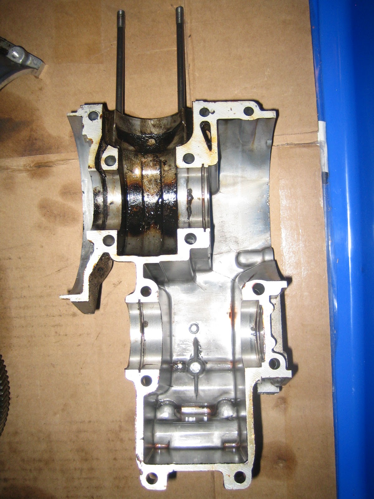
Engine with head and cylinder removed.  Looks ok from this side.
Not so good from this side.
Motor with head and cylinder removed.

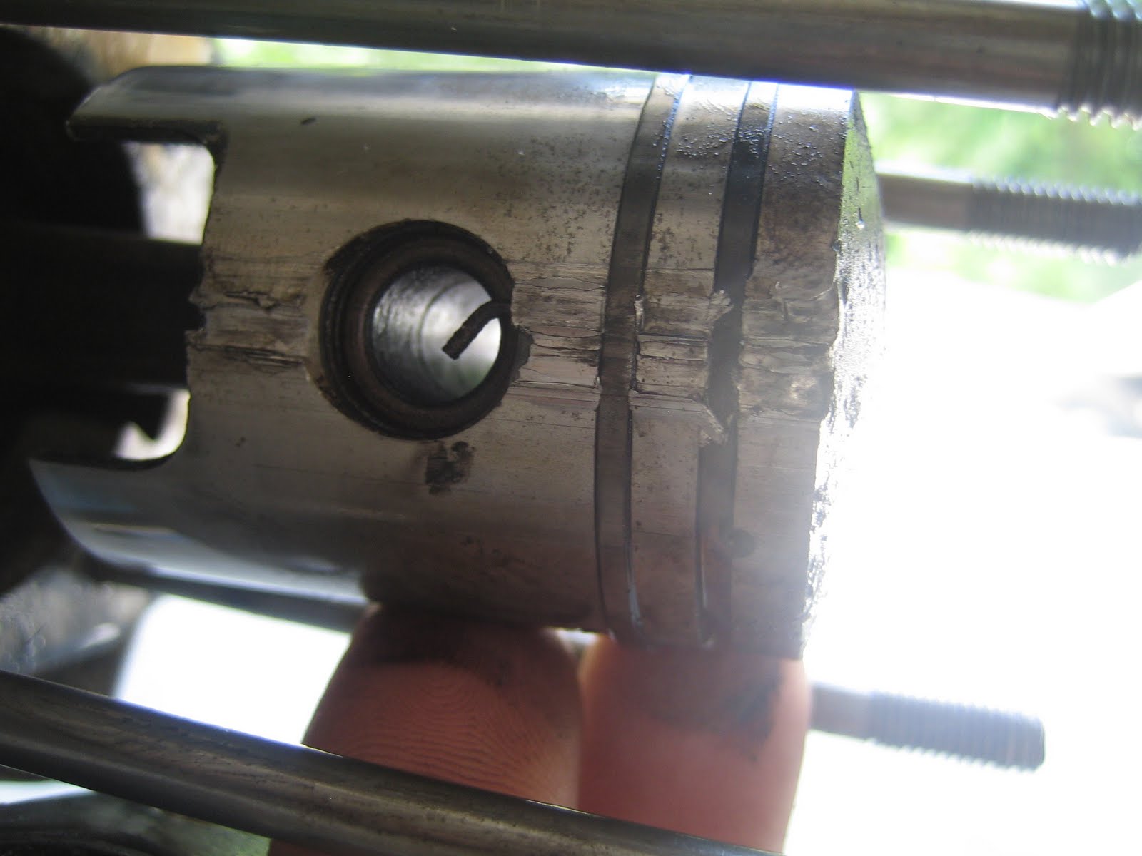
Looks like a ring broke and got wedged between the piston and cylinder and cut some serious grooves in the side of the piston.
Ouch!
Cylinder didn't fare well either.
Also dug a nice groove in the cylinder wall.  Ouch.
Piston after being removed from crank.
Side where ring dug into wall.

After finding this out, I decided to replace the piston and cylinder with a new one.  Luckily, there are a lot of moped junkies out there with parts for a ton of different models.  Puch happens to be one of the most popular, so there are a good deal of different aftermarket parts to choose from.  From an online website called treatshq.com, I found I had several options when buying  a new cylinder and piston.  I could upgrade my stock model and get a larger piston with improved porting (more intake and exhaust ports), or stick with the same size piston and get a bit more room above the top for more combustion volume.  Not sure what that means from a performance standpoint, but since the limit for motorized vehicles that don't require registration or driver's license in North Carolina is 50cc, I decided to stick with the same cylinder size and get more clearance in the head.  So I ordered some parts for $100 and waited.  

In the mean time, I decided to do a complete rebuild of the engine.  Started by yanking it off the frame.
Then pulled off the kickstand.
Then removed the 13 bolts holding the halves of the cases together and split the engine in half.  Not too complicated.

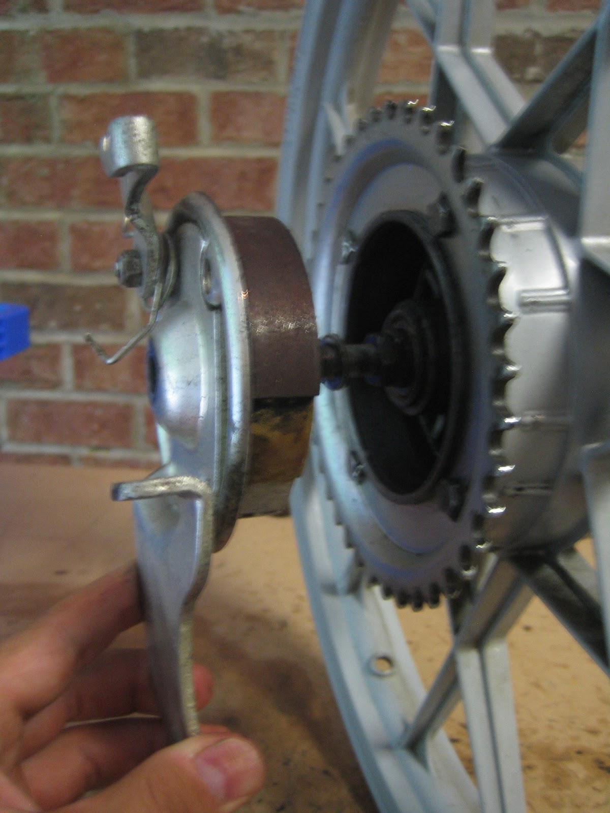
Flywheel on the left and clutch on the right.  At this point, everything looks to be in working order and decent shape, but I wanted to replace the bearings on the two shafts (main drive shaft with crank and secondary shaft connected to sprocket).  This required 4 new bearings so I ordered them and began the waiting process again.

In the mean time, decided to pull the old bearings off.  Little did I know how much trouble this would be.  First of all, getting the clutch off of the shaft requires a clutch puller because its wedged on the drive shaft.  The clutch has a tapered hole going through it that matches the taper of the drive shaft with a woodruff key in between them to prevent rotation.  But once you assemble the two together, you can't get them apart without some serious muscle.  

Clutch

The same applies on the other side with the flywheel.  A second custom flywheel puller.  

Flywheel
So I set out to make some custom tools and yank these bad boys off.

Custom Flywheel and Clutch pullers after removal
My new cylinder, piston, and head came in!
New cylinder on Left.  Note added rectangular port.
New Cylinder

New Head
Since my new head and cylinder came in, I got the idea that it'd be cool to anodize the head to match the red color of the frame.  The head in the custom above is black, so I thought I'd distinguish mine a bit by going red.  I had also just taken a class at TechShop RDU, this DIY warehouse with a bunch of equipment (lathes, mills, welders, sulfuric acid bath, etc.) you can use at will if you pay a membership fee.  So I set out to anodize the head.  I'll blog about that in another post.

Next, I went back to trying to get the old bearings off of the drive shaft and sprocket shaft.  This didn't prove to be too easy as you need a custom 3 or 4 jaw bearing puller to get these baby's off.  Fortunately, Harbor Freight had a kit of 3 of them for about $12 so I picked that up and set off after em.  I was able to get em off after about 2 hours of finageling.  Putting the new ones back on was much easier since you can just heat them up for a few minutes (I used a heat gun).  Once hot, they just slide right on.

After replacing the bearings, the engine rebuild was pretty much complete.  I just have to put the motor back together.

After doing some further inspection I noticed that the case halves have some cracks in them.  Not sure how deep these cracks go, but they don't make it all the way through.

Case Half

Other half

Cracks in the case.  See em in both sides.  Not through.
Since the cracks aren't through, I'm plowing forward.  I could replace the halves, but why not give it a shot as-is.  This engine is fairly easy to rebuild, so there aint much lost if there are issues.

With that, it's on to the new frame and wheels.